Most GPS and GNSS time servers utilize a remotely located active antenna separate from the server unit. Correct specification and installation of the antenna and cabling is paramount.
Here’s a few tips and pointers on troubleshooting or improving your time servers GPS/GNSS signal reception.
- Check time servers GNSS signal status information.
- Ensure antenna is located with good view of the sky.
- Locate the antenna away from metal structures.
- Check cable type and length is within specified limits.
- Inspect all cables for crushing and other damage.
- Ensure minimum cable bend radius is not exceeded.
- Check for poorly fitted or damaged connectors.
- Check Surge Suppressor installation and orientation.
- If fitted, check GPS/GNSS amplifier installed and orientation.
- Test antenna cable continuity.
Provided a GPS antenna has a good view of the sky, generally, a signal lock should be achieved within a few minutes.
However, in challenging conditions, such as indoor antenna location, or if the antenna has a reduced view of the sky, it can take much longer to acquire lock. In such circumstances, we recommend that the device should be left for around 1 hour after power-up to try to achieve signal lock.
If you are experiencing poor signal reception, here’s a few things to check.
GNSS Signal Status Information
TimeTools time servers provide detailed GNSS antenna and signal status information. Use the “Information” >> “GNSS Status” web page or “nts status gnss” CLI command.
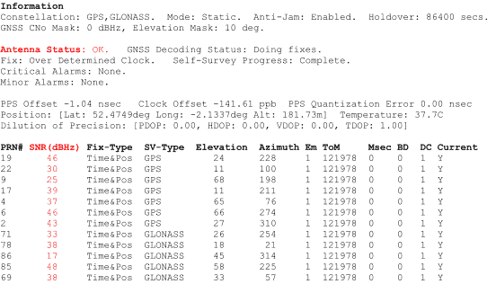
Antenna Status
The “Antenna Status” indicates if an antenna can be detected at the time servers antenna connector.
“OK” indicates that an antenna can be detected and that the current drawn at the antenna connector is within expected limits (a few milliamps). Note that a if a GPS amplifier is fitted, it will draw enough current to indicate antenna OK, regardless of whether an antenna is actually connected.
“Open” indicates an open circuit on the cable to the antenna. This generally means that the antenna is disconnected or there is a cable continuity fault.
“Short” indicates that there is a short-circuit on the cable to the antenna. This generally means that there is a cable fault and a short-circuit between the inner core and outer sheath of the cable. Often due to poorly fitted connectors or crushed cable.
Satellites in View and Signal to Noise Ratio (SNR)
The GNSS status information also indicates the number of satellite in view and provides signal to noise ratio (SNR) information for each satellite. A good installation will typically have 6 or more satellites in view for GPS only systems (T100, T300) or 10 plus for multi-GNSS systems (T550).
An antenna with a good clear view of the sky will have a number of satellites with a SNR of over 40dBHz. These satellites will have a high elevation (overhead). There may also be a number of other satellites with lower SNR values that have a lower elevation (nearer horizon).
Fewer satellites in view or poor SNR may indicate a poorly located antenna or incorrect cable specification.
Antenna Location
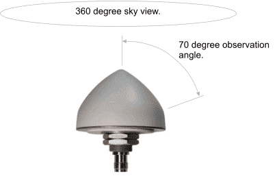
GPS systems utilize the global positioning system, which is a constellation of satellites orbiting the Earth. Therefore, to provide best results, a GPS antenna should have the best possible view of the sky. A 360 degree clear view of the sky with a 70 degree observation angle (to 20 degrees of the horizon) is ideal.
Do not locate GNSS antennas too close together. There should be a distance of at least 1m between antennas.
Locate the antenna away from other types of receivers or transmitters.
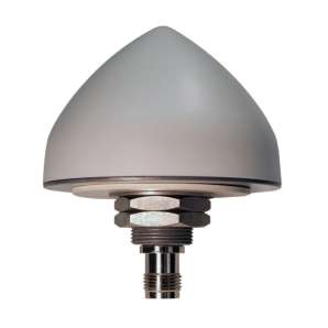
The antenna should be mounted vertically, so that the dome points straight up to the sky with the connector at the bottom.
Locate Antennas Away from Metal Structures.
Metal structures can reflect weak GPS signals and degrade receiver performance. Ensure the antenna is mounted away from metal frames, structures or enclosures. Metallized, sun-dimmed, glass contains metal flecks to reflect sunlight, which also reflects GPS signals and can cause problems.
Cable Specification
GNSS antenna installations utilize coax cable. There are many different types and specifications available. Cable type and cable length are critical to a good installation.
Note: Coax cable type is generally printed at 1m intervals along the length of the cable.
Check Cable Type and Length is within Specified Limits
A good quality 50ohm coax should be used. TimeTools recommends LMR or equivalent type coax cable. The recommended cable length for each type of cable must not be exceeded:
LMR195 – minimum length: 10m, maximum length: 50m.
LMR400 – minimum length: 30m, maximum length: 130m.
LMR600 – minimum length: 45m, maximum length: 210m.
Damaged Cable
Damaged cable can increase the signal losses associated with a specific cable type and reduce reception performance. Check the entire length of cable for crushing or other damage.
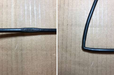
Coax cables have a minimum bend radius. Ensure that the minimum bend radius for the installed cable is not exceeded:
LMR195 – Bend Radius (installation): 13mm.
LMR400 – Bend Radius (installation): 26mm.
LMR600 – Bend Radius (installation): 39mm.
Poorly Fitted Connectors
Poorly fitted or damaged coax connectors can affect performance. Often, this can result in intermittent signal reception.
Damage can occur if cables and connectors have been pulled through trunking during installation.
Check that connectors are clean, dry and securely fitted.
Check that the connector pin is central and fully located in the connector housing and not recessed. The pin should generally be almost flush with the top of the connector.
Ensure that all threaded connectors (TNC, N-Type) are securely located – do not over tighten.
Surge Suppressors
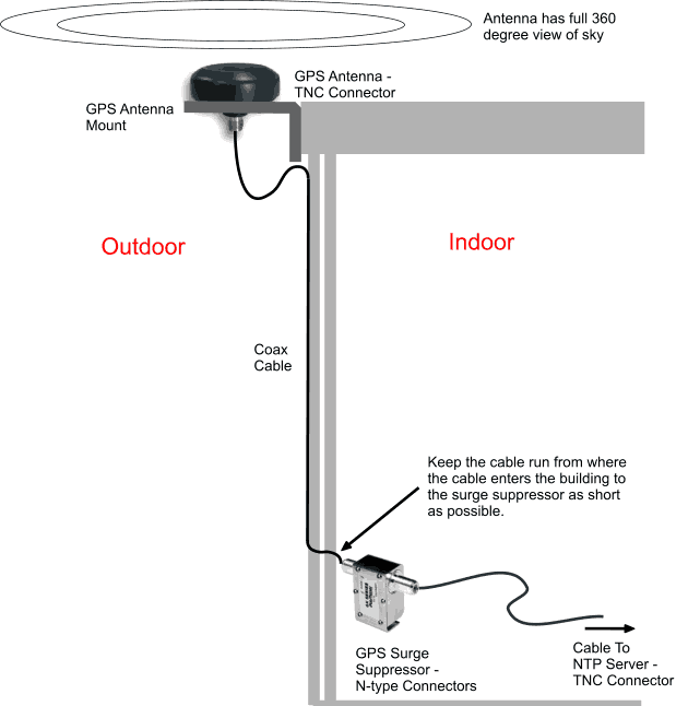
For externally mounted antennas a surge suppressor should be fitted to protect equipment from lightning strikes and other electrical surges. A suppressor should be located where the GPS antenna cable enters the building.
Ensure that the suppressor orientation is correct. The ‘Surge’ input going to the antenna and the ‘Equipment’ input to the time server.
GNSS Amplifiers
An GNSS amplifier may be used to allow longer cable lengths to be utilised.
If a GNSS amplifier is fitted, ensure that the orientation is correct. The ‘Antenna’ input should go to the antenna. The ‘Receiver’ input should go to the time server.
IMPORTANT: A single amplifier should be located at the mid point along the cable.
A single 20dB amplifier will allow extended cable runs as follows:
LMR400 – minimum length: 145m, maximum length: 250m
LMR600 – minimum length: 225m, maximum length: 390m
Testing Cable Continuity
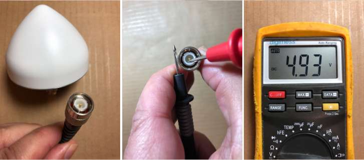
The time server powers an active GNSS antenna from the antenna connector at the rear of the unit.
A volt meter can be used to check the continuity of the cable to the antenna.
IMPORTANT: The time server must be powered and the antenna cable connected to the server to test cable continuity with a volt meter.
Remove the antenna connector from the under side of the antenna. Set the volt meter to measure DC volts.
Place the negative (black) probe on outer barrel of the connector and the positive (red) probe on the connector center pin.
The volt meter should read in the region of 4.8V to 5V. No voltage generally indicates a cable continuity fault. A lower voltage may indicate a short circuit in the cable.
IMPORTANT: Do not attempt to measure the impedance or resistance of the cable to the antenna. You may damage the antenna!
The same test can also be performed on the input to the surge suppressor from the time server.
Typical GPS/GNSS Installation
Please refer to the surge suppressor engineering specification and installation guide for more information on installation best practice:
SPP-GPS Installation Guide – Please read before installing.
SPP-GPS Engineering Specification
Useful Links
https://www.timesmicrowave.com/Calculator
https://www.tallysman.com/app/uploads/2020/04/Timing-Antenna-Installation-v3.0.pdf

| About Andrew Shinton Andrew Shinton is the joint founder and Managing Director of TimeTools Limited. He has a BSc (Hons) degree in Computer Science. Andrew has over 20 years experience of GPS systems and Network Time Protocol (NTP) in the Time and Frequency Industry. |
LMR® is a registered trademark of Times Microwave Systems.